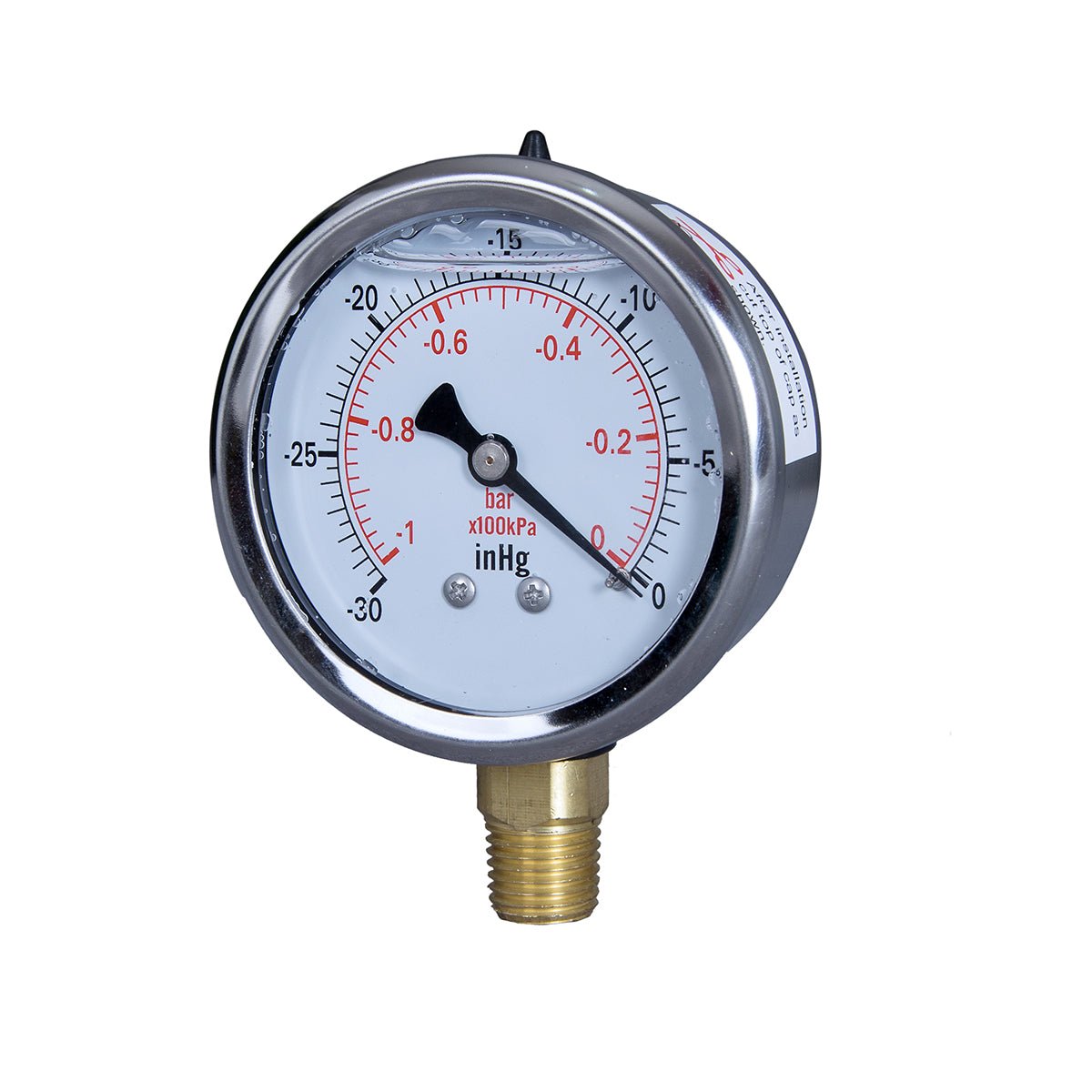
Liquid Filled Hydraulic Pressure Gauge: Choose, Install, Read (2026)
JIVTOA liquid filled hydraulic pressure gauge is the only sensible choice on any hydraulic circuit: glycerin filling dampens the pressure ripple that gear and piston pumps generate on every rotation, plus the engine and chassis vibration that shakes a dry gauge's movement apart within months. Pick the range so normal operating pressure sits in the dial's middle third (steady loads ≤75% of full scale, cyclic loads ≤65%), tap the port at the pump outlet or manifold, and learn to read the damped needle — because once the fluid has smoothed out the noise, what remains is genuine system behavior.
This tutorial walks through the whole process: why hydraulics are the hardest duty a gauge can face, which specs actually matter, a six-step installation procedure, and a diagnostic table for interpreting readings after install. If you're new to the category, start with our complete liquid filled pressure gauge buyer's guide first — this post assumes the basics.

Key Takeaways
- Gear pumps and piston pumps produce pressure ripple on every rotation; combined with engine vibration, this destroys dry gauge movements in months. Glycerin fill absorbs both.
- Size the dial so steady pressures stay ≤75% of full scale and cyclic pressures ≤65%. Most mobile hydraulic systems run 150–250 bar (~2,200–3,600 psi), so high-range dual psi/bar dials are the norm.
- Tap at the pump outlet or at/before the manifold — never in a dead leg where oil sits stagnant and reads late.
- A filled gauge turns noise into signal: slow creep usually points at the relief valve; a gradual sag under load points at internal leakage.
Why Hydraulic Duty Is the Hardest Duty a Pressure Gauge Faces
Hydraulics attack a gauge from two directions at once. First comes pulsation: gear pumps displace discrete pockets of fluid per tooth, and piston pumps per piston stroke, so line pressure ripples at pump frequency every single rotation — often several hundred pulses per minute, with swings large enough to visibly flog the pointer. Second comes vibration: the diesel engine, the chassis, and the boom cylinders all shake whatever panel the gauge is bolted to.
On a dry gauge, that combination grinds the unlubricated pinion and sector gears until play develops, then the needle sticks, flutters uselessly, or falls off zero entirely (Swagelok). We see returned gauges from hydraulic duty with worn movements that look years old after one season. The comparison isn't close — we documented the failure modes side by side when explaining why dry gauges die fast on vibrating equipment in our oil filled vs dry pressure gauge comparison. Glycerin fill solves the problem mechanically: the fluid mass resists rapid pointer motion, damping flutter from both ripple and shake, while continuously lubricating the movement's wear points (Mid-West Instrument).

One honest trade-off: damping adds response lag. A liquid filled gauge won't show every transient spike — that's the point — but it also can't capture peak values during fast cycling. If you need true peak capture on a test stand, pair the filled gauge with a transducer or a snubber vs liquid filled gauge decision guide.
Spec Selection Walkthrough: Range, Fill Fluid, Mounting, Case
Range: put normal operation in the middle third
The range rule has two clauses. For steady pressure, size the dial so normal operating pressure stays at or below 75% of full scale (Ashcroft). For cyclic duty — which describes nearly every hydraulic system — tighten that to 65%, because repeated flexing near the top of the Bourdon tube's travel fatigues it far faster (Hiqool). The upper quarter of any dial is also where readable accuracy is poorest, so a gauge running pinned near max tells you less precisely than one loafing in the middle third.
Practically, most mobile and industrial circuits run 150–250 bar (roughly 2,200–3,600 psi). A typical excavator hydraulic gauge or hydraulic pump pressure gauge therefore wants a 0–400 bar / 0–6,000 psi class dial, not a general-purpose 0–100 psi unit. Always order dual-scale psi/bar — North American service manuals speak psi, European schematics speak bar, and a single-scale dial guarantees someone misreads it.
Fill fluid: glycerin covers most hydraulic work
Standard glycerin fill handles ambient service from roughly -20°C to +60°C, which covers most equipment sheds and most climates — but not cold-soaked machines started outdoors in deep winter. Below about -20°C glycerin thickens and the needle turns sluggish until the case warms; if your machines cold-start outside, discuss low-temp fill options with the supplier rather than accepting a standard unit. Above the envelope, thinning fluid reduces damping. Neither extreme damages the gauge permanently, but both degrade readability exactly when you're relying on it.
Mounting: match the port you have
The 1/4" NPT connection is the industry-standard hydraulic test port size, and both lower-mount (radial) and back-mount (axial) configurations exist to suit it. Lower mount suits panel holes and direct threading into vertical ports; back mount with a front flange suits bracket-mounted panels where the case must project forward. Match the configuration to the physical install before price-shopping anything else.
Case: stainless for washdown and off-road
For stationary power packs indoors, a plated steel or black case survives fine. Mobile equipment — sprayers, excavation iron, ag machinery — sees mud, fertilizer, pressure washing, and road salt, and that combination eats plated cases around the bezel and window seal. Stainless cases cost more upfront and outlast the machine in those environments. This is the single most common upgrade our OEM customers specify for off-road builds.
Installation Best Practices: Six Steps
- Tap at the pump outlet, or at/before the manifold. You want to see system pressure where it's generated and controlled, not downstream decay. Avoid dead legs — stagnant-oil stubs read late, trap debris, and collect sludge that slowly blocks the Bourdon inlet.
- Keep the connection short and serviceable. Thread directly into the port where possible. If you need a remote line, slope it so oil drains back and include an isolation valve (gauge cock) so the gauge can be swapped without dumping the circuit.
- Add pulsation control on severe duty. On high-frequency piston-pump ripple, an upstream snubber or orifice extends movement life further; the filled case handles most jobs alone, and our snubber vs liquid filled gauge breakdown explains when each is the right tool.
- Seal threads properly. Use PTFE tape or rated pipe dope on the male threads only, leaving the first thread bare so sealant can't migrate into the port. Never let compound enter the gauge internals.
- Tighten with a wrench on the hex flats. Torquing through the case twists the bayonet seal and is the classic cause of fill-fluid leaks we see on warranty returns. Snug per fitting grade — NPT seals on thread interference, not brute force.
- Orient for the reader, not the installer. Mount so the dial faces the operator's standing eye line, ideally vertical with the connection down. A correctly ranged gauge is worthless if whoever troubleshooting at 6 a.m. can't read it from the access side.
Interpreting Readings: Healthy Patterns vs Trouble Signs
After install, the damped needle becomes a diagnostic instrument. Because the fill strips out pump ripple and vibration, remaining motion reflects actual system behavior:
| Needle pattern | Likely meaning | Action |
|---|---|---|
| Steady, slight drift with load changes | Healthy — pressure follows demand | None; baseline it |
| Small, slow oscillation between two values | Relief valve or unloader hunting | Check relief setting, inspect poppet/seat |
| Slow upward creep at idle, engine warm | Relief valve leaking or worn pump internal leakage raising standby pressure | Verify relief valve; check case drain flow |
| Gradual sag under sustained hold | Internal leakage (cylinder seals, valve spools) | Isolate sections to localize |
| Needle pinned at max | Overpressure or failed damping — stop and investigate immediately | Shut down; verify with a known gauge |
| No motion at all under load | Blocked port/dead leg or failed gauge | Isolate, back-probe with a second gauge |
Two habits make hydraulic system pressure monitoring genuinely predictive. Log the idle (standby) pressure weekly — creeping standby pressure is the earliest cheap symptom of pump wear. And compare gauges across a machine's functions periodically; one circuit drifting away from its siblings localizes a fault without any instruments beyond the dials already installed.
What OEM Builders Standardize On
We supply gauges to OEM builders of hydraulic power packs and agricultural sprayers, and their volume orders reveal a consistent pattern worth copying: 2.5" dials with dual psi/bar scales, 1/4" NPT lower mount as default, glycerin fill, ranges chosen so nominal working pressure lands mid-dial, and stainless cases wherever washdown or weather applies. Equipment builders who ship thousands of units have settled on these specs because they minimize warranty claims — a useful filter when you're specifying your own hydraulic pump pressure gauge.
Recommended: JIVTO 2.5" Liquid Filled Hydraulic Pressure Gauge
The JIVTO 2.5" Liquid Pressure Gauge packages those OEM-standard specs into a single part number: glycerin filled for pulsation and vibration damping, 1/4" NPT in your choice of lower mount or back mount, dual psi/bar scale, Bourdon tube sensing with brass internals, ranges up through the 0–300+ psi classes common in hydraulic work (high-bar classes available for 150–250 bar mobile systems), and stainless case options for washdown and off-road duty.
Factory-direct from our Wenzhou facility with 15+ years of gauge manufacturing behind it. Request a quote for volume pricing: MOQ approximately 200 units, typical lead time around 30 days, and OEM logo dial printing available for equipment builders who want their brand on the panel.
Frequently Asked Questions
Can I use a regular dry gauge on a hydraulic system?
You can, but expect a short life. Continuous pressure ripple from the pump plus machine vibration wears out a dry gauge's unlubricated movement in months on many installations, and the fluttering pointer makes the reading unreliable long before total failure. A liquid filled hydraulic pressure gauge costs more once; a dry gauge on hydraulics costs more every season.
What pressure range should my hydraulic gauge be?
Size so steady operating pressure stays ≤75% of full scale and cyclic pressure ≤65%. Since most mobile hydraulic systems run 150–250 bar (~2,200–3,600 psi), that usually means a 0–400 bar / 0–6,000 psi class dial. Keeping normal operation in the dial's middle third maximizes readable accuracy and Bourdon tube life.
Why does my hydraulic gauge needle vibrate even though it's liquid filled?
Some fine residual motion is normal — the fill reduces amplitude, it doesn't freeze the needle. But if the pointer still flutters violently, check for a partially clogged inlet (restricting damping effectiveness), an air pocket from incomplete case filling on a cheap unit, or pressure spikes beyond what glycerin damping alone can absorb — that last case is where a snubber earns its place upstream.
Where should the gauge be tapped into a hydraulic circuit?
At the pump outlet or immediately at/before the main manifold, so you read true system pressure. Never in a dead leg: stagnant-oil branches respond slowly, accumulate debris against the Bourdon inlet, and eventually block. Keep the run short, include an isolation valve, and orient the dial toward the operator's eye line.